


"Ada" Pressure Test Procedures
The "Ada" pressure test was developed at the EPA's Robert S. Kerr Environmental Research Laboratory in Ada, Oklahoma. The test is useful in cases where injection is through tubing without a packer, in wells with only casing and open perforations (tubing and packer removed), and in dual injection/production wells. The test consists of determining the static fluid (Figure 1) level in the tubing/casing annulus, applying air pressure (Figure 2) to the annulus to depress the fluid level down to the perforations, and comparing the final stabilized air pressure (Figure 3) with the computed air pressure needed to depress the fluid level to the known depth of perforations. A second test is used to demonstrate the integrity of the tubing and packer below the depth of upper productive perforations in dual injection/disposal wells.
Requirements
- The test must be conducted in accordance with the instructions on Form H-5. Note that the well must have a static fluid level high enough above the uppermost perforations to meet the minimum test pressure requirements for a standard pressure test (instruction 4(c)). With 9.5 ppg brine, the required fluid level ranges from 405 to 1012 feet above the perforations for a 200 to 500 psi test pressure.
- The static fluid level, the depth of perforations, and the specific gravity of the annulus fluid must be accurately measured or known.
- The injection well must be shut-in and the pressure stabilized. The well must be shut in long enough before the test to prevent temperature-induced pressure anomalies.
- The annulus fluid level may not be above the base of usable quality ground water unless the casing is cemented from the land surface through the base of usable quality ground water.
- For wells injecting through tubing and packer set below production perforations, the tubing and packer integrity must also be demonstrated in the interval between the production perforations and the disposal/injection perforations. This may be done by one of two methods: A) a radioactive tracer survey may be run through tubing, while injecting at the maximum authorized injection pressure, if the survey demonstrates the absence of any leaks; or B) an "Ada" pressure test may be run inside the tubing if the "Ada" test requirements can be met.
Procedure
- Accurately measure the fluid level in the tubing/casing annulus. Provide documentation of the measurement, such as an "Echo-Meter" chart or wireline measurement record, as a supplement to Form H-5.
- Determine the specific gravity (or density) of the tubing/casing annulus fluid. Include a statement of how the specific gravity was determined.
- Compute the air pressure necessary to displace the fluid level down to the perforations. Include calculations with Form H-5. Note that it may be advisable to use an inert gas (such as nitrogen) instead of air if the annulus fluid contains hydrocarbons, which may become flammable in the presence of air.
- Shut in the well long enough for wellbore pressure and temperature to stabilize.
- Apply the calculated air pressure to displace the fluid level to the perforations and allow the pressure to stabilize. If the well will not stabilize at the calculated air pressure, the test is either inaccurate (due to bad fluid level measurement or inadequate shut-in period) or indicates a mechanical integrity failure (due to air pressure bleeding off above the fluid level/perforations).
- The fluid level must be static and the air pressure must stabilize at the calculated pressure for AT LEAST 60 MINUTES (standard time requirement for air pressure H-5 test against a packer).
- If the "Ada" pressure test is inconclusive, the well should be shut in and a temporary packer or bridge/wireline plug run in for a conventional pressure test. If the "Ada" test indicates a mechanical integrity failure, the well should be shut in immediately and repaired or plugged within 60 days.
Sample Calculations
- The static fluid level in a wellbore is measured to be at a depth of 2530 feet below ground surface. The uppermost perforation is at a depth of3124 feet. The fluid in the annulus/casing is 9.5 lb./gallon oilfield brine.
- Determine the height of the water column above the perforations. Do this by subtracting the depth of perforations from the static fluid level:
3124 - 2530 = 594 feet of fluid above the perforations. - Calculate the fluid pressure gradient by multiplying the weight of the water by a conversion factor.
( 9.5 lb./gal. x 0.052) = 0.494 psi/ft
(Note: 0.052 is the conversion factor between lb./gal and psi/ft). - Calculate the gas pressure needed to displace the water by multiplying the feet of fluid by the fluid pressure gradient:
594 feet of 9.5 lb./gal. brine is: 594 ft of fluid * 0.494 psi/ft = 293.44 psi.
Therefore, the annulus pressure must stabilize at a pressure of 293 psi. for 60 minutes to demonstrate the mechanical integrity of the well. - If the stabilized test pressure is less than the computed value, then a leak ezists at a depth which corresponds to the measured pressure. For example, if the stabilized pressure is 230 psi instead of 293 psi, then there is a leak 465 feet below the measured fluid level (230 psi / 0.494 psi/ft = 465 ft.) which corresponds to a depth of 2,995 feet (2,530 fluid level + 465 feet = 2,995)
Testing a Well Without Tubing
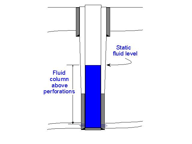 Figure 1
Static conditions at the start of the test
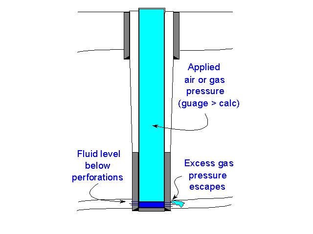 Figure 2
Applying gas test pressure, excess gas
pressure bleads away into the formation
as fluid level drops below the perforations
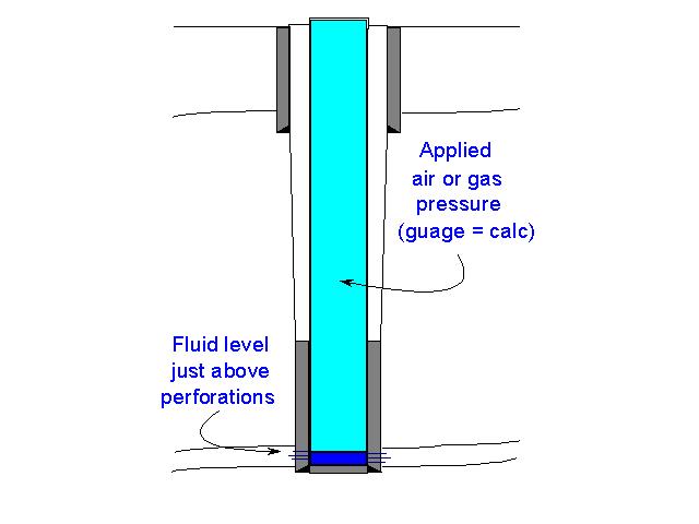
Figure 3
Mechanical integrity is demonstrated
by a stabilzed test pressure equal to
the calculated value
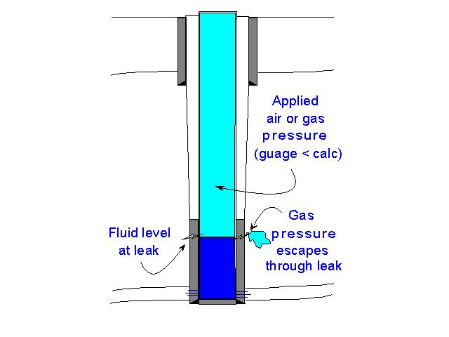 Figure 4
A leak is indicated by test pressure
being less than the calculated value
Testing a Well with Tubing but No Packer
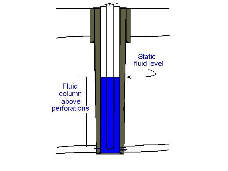 Figure 1
Static conditions at the start of the test
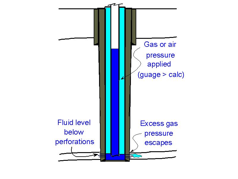 Figure 2
Applying gas test pressure, excess gas
pressure bleads away into the formation
as fluid level drops below the perforations
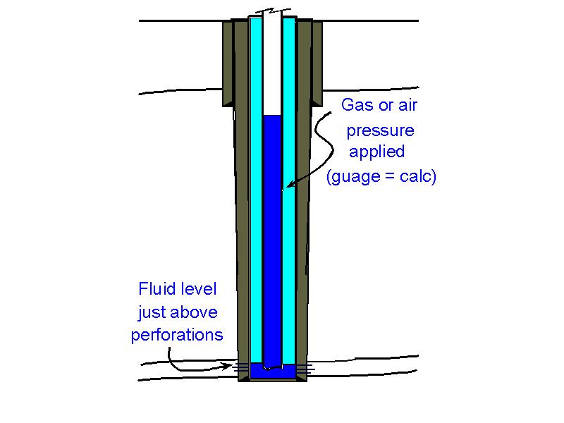 Figure 3
Mechanical integrity is demonstrated
by a stabilzed test pressure
equal to the calculated value
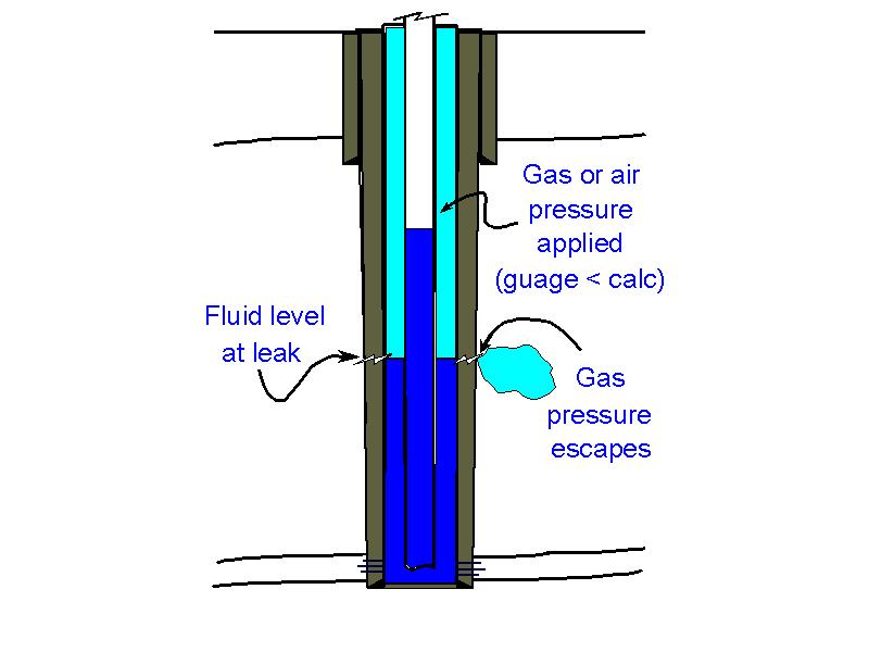 Figure 4
A leak is indicated by test pressure
being less than the calculated value
Testing Well with Tubing and Packer with Dual Production/Injection Completion
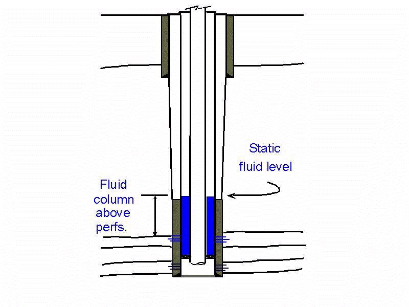 Figure 1
Static conditions at the start of the
annulus test
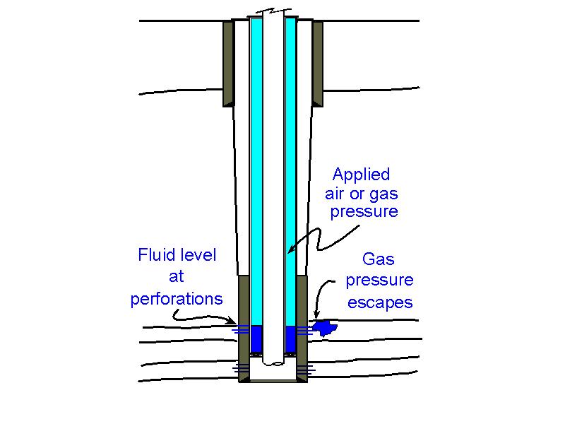 Figure 2
Applying gas test pressure, excess gas
pressure bleads away into the formation
as fluid level drops below the perforations
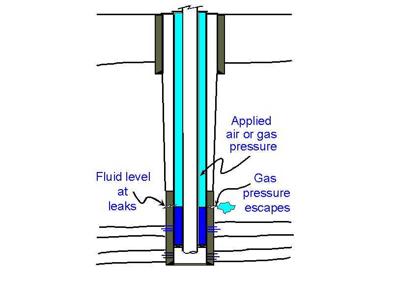 Figure 3
Mechanical integrity is demonstrated by a stabilzed test pressure equal to the calculated value a leak is indicated by test pressure being less than the calculated value
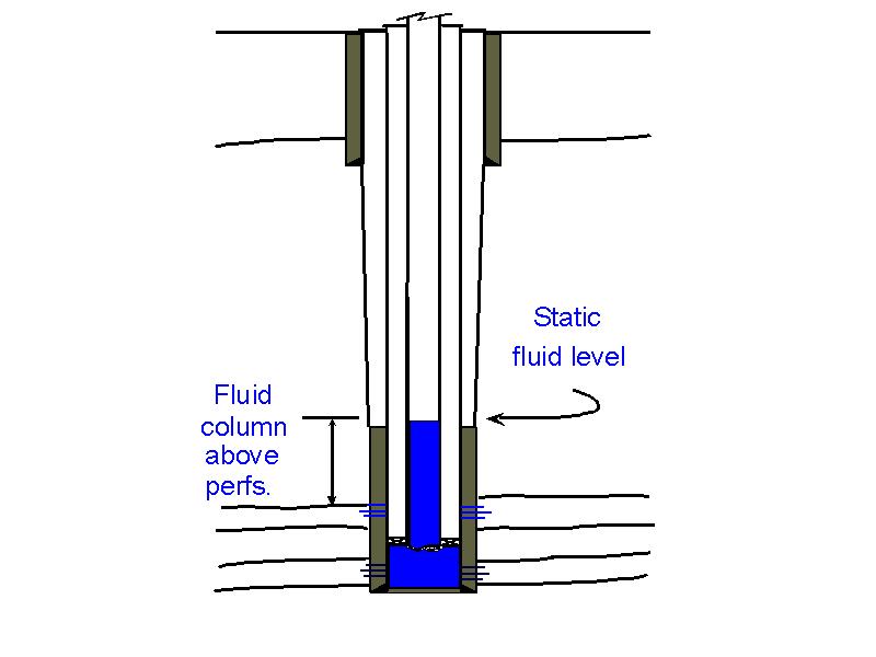 Figure 4
Static conditions at the start of the
tubing and packer test
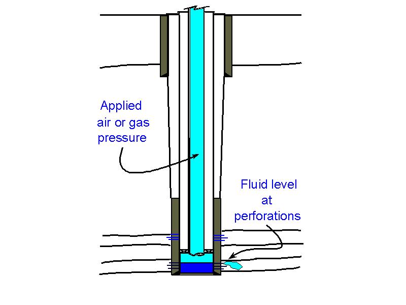 Figure 5
Applying gas test pressure, the fluid level in the tubing is depressed past the packer, excess gas pressure bleads away into the formation as fluid level drops below the perforations
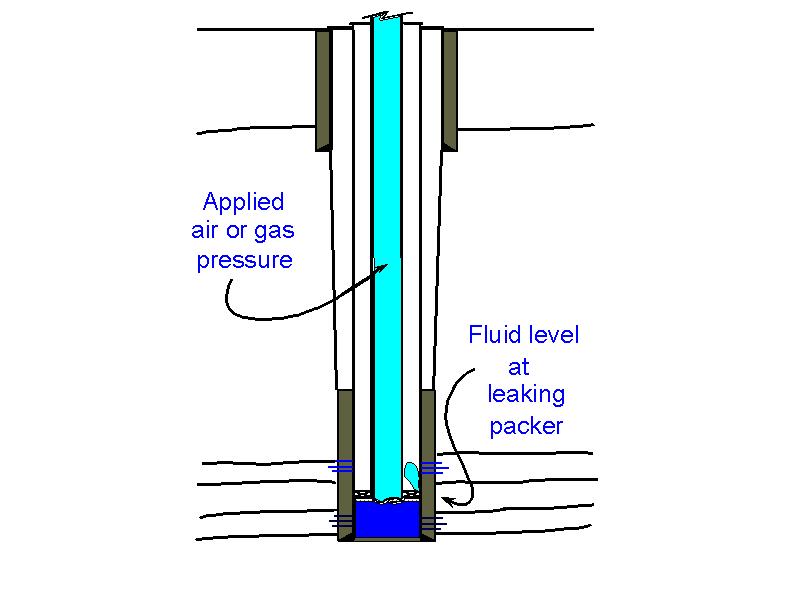 Figure 6
A leak is indicated by test pressure being
less than the calculated value.